A high reduction requirement does not automatically justify putting two worm stages in one housing. You need to relate the required output speed to motor speed, calculate usable torque after efficiency losses, and confirm that the gearbox can dissipate heat throughout the duty cycle before comparing it with other gearbox types.
Key takeaways
- Use two worm stages when one stage cannot deliver the required reduction ratio.
- Calculate output speed by dividing motor speed by the total reduction ratio.
- Check efficiency and thermal capacity before selecting a gearbox by torque rating alone.
- Give suppliers ratio, speed, torque, duty cycle and safety details in writing.
What a double reduction worm gearbox changes
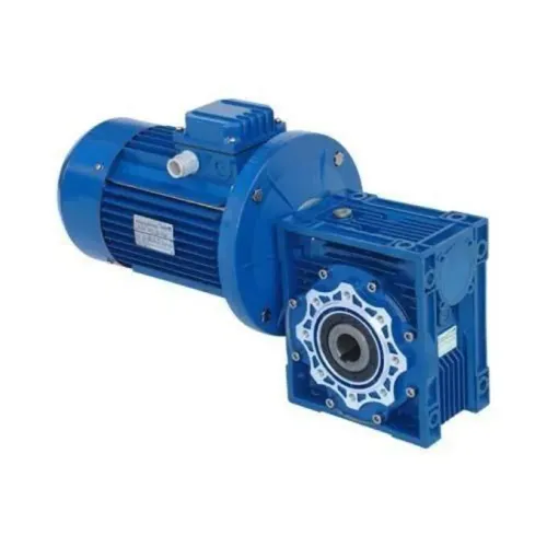
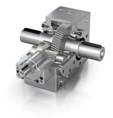
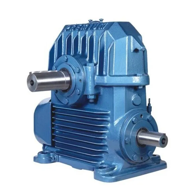
A double reduction worm gearbox contains two reduction stages arranged in series. The motor drives the first worm and wheel; its intermediate shaft drives a second worm and wheel before the output shaft.
The nominal reduction ratio equals the first stage ratio multiplied by the second, so two 10:1 stages provide a nominal 100:1 reduction without forcing one worm to use an extremely low lead angle.
Choose the extra stage when:
- The motor runs far faster than the required output, and the target ratio exceeds a practical single-stage worm gearbox range.
- Two moderate ratios provide the required output speed without excessive sliding, heat or torque limits in one stage.
- The machine has room for a larger or longer housing, plus the additional shaft, bearings and mounting space.
The trade-off is mechanical and thermal. Compared with a single-stage worm gearbox, the double-reduction design adds another gear mesh, shaft, bearing set and source of backlash. Reversing motion must overcome backlash from both meshes, which reduces positioning accuracy and accelerates wear during frequent direction changes.
A high ratio alone does not justify the arrangement. Reject it when continuous duty makes sliding losses and heat difficult to remove, when efficiency matters more than compact purchase cost, or when reversing accuracy demands low backlash. Check whether a helical, bevel-helical or planetary gearbox provides the required reduction with lower losses.
Confirm the gearbox’s thermal rating, output torque and space requirements before treating the ratio as the deciding factor.
Calculate the ratio, output speed and usable torque
Begin with the speed requirement: required ratio = input rpm ÷ target output rpm. A 1,440 rpm motor and 14.4 target output rpm give a 100:1 ratio calculation; two 10:1 stages produce that nominal ratio.
- Confirm the motor’s input rpm and calculate the nominal ratio from the target output rpm.
- Check the manufacturer’s output-speed data at that input speed. The actual output speed can differ from 14.4 rpm because motor slip, gearbox losses and load conditions affect running speed; do not treat the nominal figure as a guarantee.
- Calculate motor shaft torque: torque in N·m = 9,550 × motor power in kW ÷ input rpm. Then estimate output torque as motor torque × total ratio × total efficiency.
- Multiply that torque by the application service factor for continuous duty, shock loading, starts per hour and reversing. Compare the resulting design torque with the gearbox rated output torque.
| Value | Calculation or check | Why it matters |
|---|---|---|
| Nominal speed | 1,440 ÷ 100 = 14.4 rpm | Sets the starting estimate |
| Usable torque | Motor torque × 100 × total efficiency | Accounts for losses through both meshes |
| Design torque | Usable torque × service factor | Covers duty severity and transients |
Include duty cycle, acceleration torque and stopping torque in the selection. Check overhung radial load, axial load, shaft diameter, key capacity and bearing limits for the actual sprocket or pulley; the catalogue torque figure does not prove that the output shaft or bearing can carry a nearby load.
Check efficiency and thermal capacity before torque capacity
Two 70% worm meshes deliver approximately 49% combined worm gearbox efficiency before bearing and seal losses. The remaining input power becomes heat generation inside the housing, so a torque calculation can become a thermal capacity problem before the gears reach their rated torque.
1. Do not predict efficiency from ratio alone. Lead angle, sliding velocity, lubrication, surface finish, load and running-in condition can change the real figure between two gearboxes with the same nominal ratio.
2. Check the manufacturer’s thermal rating at the actual input speed, ambient temperature, mounting orientation and duty cycle. Low output speed can leave an attached fan moving too little air to remove the heat.
3. Confirm the specified lubricant, fill quantity and approved change interval. Lubrication compatibility matters: automotive or generic extreme-pressure oil can damage a bronze worm wheel when its additives are unsuitable.
4. Verify the oil level for the exact mounting position. Changing orientation without the maker’s instructions can starve bearings, reduce splash coverage or leave the worm mesh inadequately lubricated.
5. Include VFD operation in the check. Low-frequency running can reduce motor-fan cooling, while high-frequency running can exceed the gearbox input-speed limit; neither setting removes the gearbox’s thermal or mechanical limits.
Compare the double-worm option with alternatives and safety requirements
For the same 100:1 application, choose a double-worm unit only after comparing energy, heat and control performance—not ratio alone. A single-reduction worm gearbox is simpler and adequate when its available ratio, torque and thermal rating meet the duty.
| Option | Input power and heat | Service life, backlash and noise | Footprint and operating cost |
|---|---|---|---|
| Double-worm | Highest sliding loss; check thermal capacity carefully | Two meshes add wear, backlash and torsional wind-up during reversal; quiet operation | Compact ratio solution, but cooling, oil and lost-energy costs can dominate |
| Single worm | Lower losses than two worm stages at a suitable ratio | Simpler, with less backlash and fewer wear points | Usually smaller and cheaper when its ratio and rating fit |
| Helical-worm gearbox | Lower sliding losses and heat than all-worm gearing | Longer service life and good noise performance | A useful helical gearbox comparison when efficiency matters |
| Bevel-helical gearbox | Efficient right-angle transmission with lower heat | Good durability and controlled backlash | Larger or costlier than a worm unit; lower total operating cost in continuous duty |
| Planetary gearbox | High torque density and low backlash | Suits precision and repeated reversing | Higher purchase cost, but reduced energy loss can repay it |
Reject a double-worm choice for continuous high-duty operation where energy losses dominate, frequent reversing, high positional accuracy or severe backdriving risk. A planetary gearbox deserves priority for precision; a bevel gearbox suits efficient right-angle transmission.
Self-locking depends on lead angle, wear, lubrication, vibration, load and geometry. A gearbox that resists backdriving is not a certified holding device. Use a separately rated brake or positive restraint for hazardous descent or reverse motion, and include backlash and torsional wind-up from both meshes in the reversal calculation.
Turn the calculation into a supplier specification
Turn the calculation into a supplier specification that describes the machine, not just its reduction ratio. Perfect Engineering Solutions can use these details to compare gearbox, motor and VFD combinations for an industrial installation in Coimbatore; the useful comparison is documented operating fit, not the lowest catalogue price.
1. Provide motor power, motor rpm, VFD frequency range, required output rpm, calculated ratio, continuous output torque, peak output torque, service factor, starts per hour, reversing frequency, operating hours, ambient temperature, mounting orientation, shaft arrangement, brake requirement and driven-load details.
State whether the load uses a sprocket, pulley or coupling, its diameter, overhung distance, radial load, axial thrust, acceleration torque and stopping torque.
2. Ask for the gearbox’s nominal ratio, measured or guaranteed output speed at your input speed, rated output torque, thermal rating, efficiency data, allowable input speed, backlash, radial-load limit, axial-load limit, lubricant specification and approved mounting positions.
If continuous power loss is high or thermal margin is inadequate, request a helical, bevel-helical or planetary alternative before ordering.
3. Request written confirmation that the output shaft, key, bearings and seals suit the actual sprocket, pulley or coupling, including its load and mounting distance. Include the motor’s low-speed cooling, maximum VFD frequency and any brake or positive restraint required; a gearbox that resists backdriving is not a safety brake.
Related products
 | WORM GEARBOX ₹100000 PERFECT ENGINEERING SOLUTIONS WE HAVE WIDE RANGE PRODUCTS OF MOTOR, GEARBOX, PUMPS , VFD DRIVES , CABLES, ETC... View product → |
 | Electric Motor ₹5100 Gear Type Worm Material Aluminium Orientation Horizontal Mounting Flange Output Torque 350Nm Input Speed 1400 rpm WORM GEARBOX W SERIES... View product → |
Frequently asked questions
What changes when a gearbox uses two worm reduction stages?
The motor drives a first worm and wheel, whose intermediate shaft drives a second worm and wheel. The total ratio multiplies across both stages, increasing reduction while adding losses and heat.
How do you calculate output speed and usable torque?
Divide motor speed by the total reduction ratio to find output speed. Estimate usable output torque from motor torque, the two stage efficiencies and the gearbox service factor.
Why check thermal capacity before torque capacity?
Worm gears lose more power as heat than many geared alternatives. A gearbox can meet the torque rating yet overheat when duty cycle, ambient temperature or continuous operation exceeds its thermal capacity.
What information should you give a gearbox supplier?
Provide motor speed and power, required output speed, calculated torque, duty cycle, operating hours, ambient temperature, mounting position, load characteristics and safety requirements.
Related products
 | Gear Box 0.5 Iron Worm Gear Box, Size: 30-150 ₹4500 Material Cast Iron Power 0.5 Gearing Arrangement Type Worm Size 30-150 Orientation Horizontal Mounting Foot View product → |
 | Gear Box ₹13500 Perfect Engineering Solutions - Trader-Retailer of Geared Motor, Electric Motor & vfd Drive Since 2013 in Coimbatore, Tamil Nadu. View product → |
 | Gear Box ₹4700 Perfect Engineering Solutions - Trader-Retailer of Geared Motor, Electric Motor & vfd Drive Since 2013 in Coimbatore, Tamil Nadu. View product → |