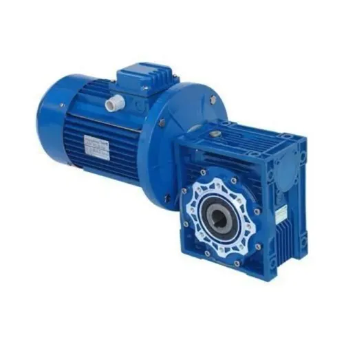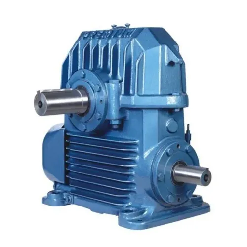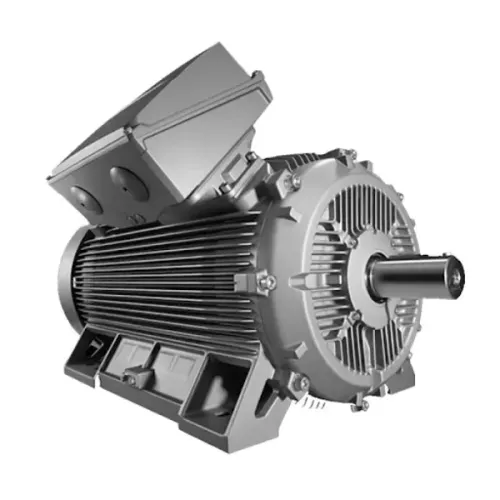
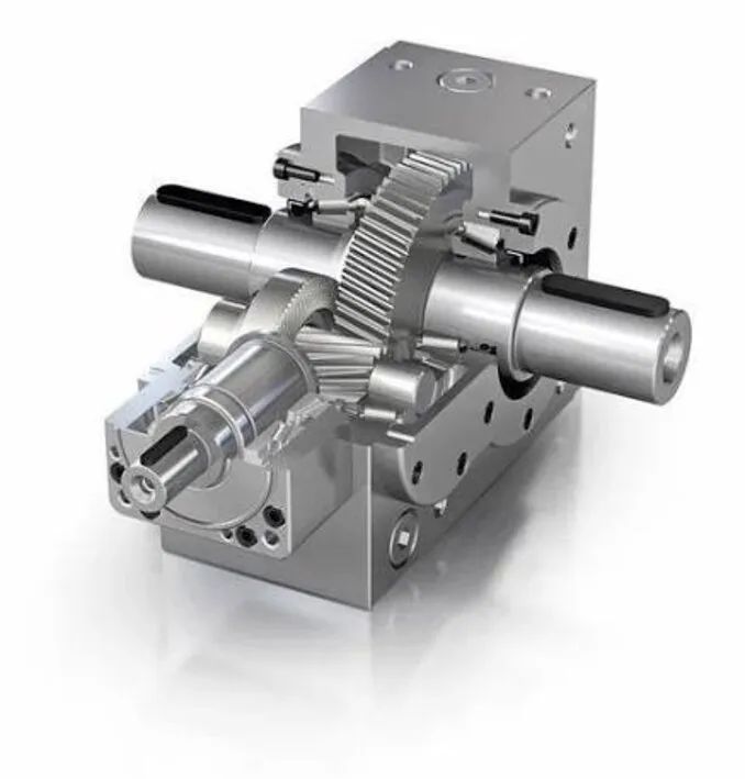
A bevel-helical gearbox turns a motor’s high-speed rotation through 90 degrees, then uses helical gear stages to reduce speed and multiply torque. By the end, you will be able to calculate the torque a machine needs, distinguish continuous capacity from transient loads, and specify the gearbox, mounting, lubrication and cooling checks that prevent premature failure.
Key takeaways
- Calculate required torque from load, speed, efficiency and service factor.
- Include starting, braking, reversing and driven-load shock in the selection.
- Check continuous torque against the gearbox’s thermal rating.
- Give suppliers speed, torque, duty cycle, load type and mounting details.
How the bevel and helical stages turn motor power into torque
A bevel-helical gearbox changes shaft direction at the bevel gear stage: the motor drives a bevel pinion, which meshes with a bevel wheel and turns power through 90 degrees. The following helical gear stages reduce speed progressively while carrying the increased torque.
That arrangement creates a compact right-angle gearbox for conveyors, mixers and other industrial machines. For a first estimate, use T = 9550P/n, where P is transmitted power in kW, n is speed in r/min and T is torque in N·m.
With reduction ratio i, output speed is approximately motor speed divided by i. Ideal output torque is motor torque multiplied by i; gear-mesh and bearing losses reduce the actual value. Low speed does not permit unlimited torque because tooth strength, shafts, bearings, housing stiffness and heat can become the limiting factors.
Do not compare only the catalogue output-torque figure. Check:
- Continuous load torque and duty-cycle duration
- Starting, reversing and shock peaks
- Gear-tooth bending and pitting
- Radial and axial bearing loads
- Key, shrink-disc or splined output capacity
The bevel stage creates axial force, so bearing selection, preload and alignment matter. Soft-foot, pipe strain, a misaligned coupling or an incorrectly tensioned chain can cause noise, seal damage and early failure. The published rating is continuous mechanical capacity under stated speed, lubrication, service factor and life—not a guaranteed peak torque.
Calculate the torque the machine actually needs
Use T = 9550P/n for the output torque calculation: T is N·m, P is motor power in kW, and n is shaft speed in r/min. With a 15 kW motor at 1,450 r/min, a 20:1 reduction ratio gives roughly 72.5 r/min output speed. At 94% efficiency, output torque is about 1,860 N·m.
Size against the machine’s real load, not that calculated maximum:
- Establish the continuous load torque at the gearbox output shaft, including friction and any incline or lifting force.
- Calculate acceleration torque from the driven inertia and required acceleration time; include the reflected motor and load inertia.
- Record starts per hour, reversing, braking, loaded starts and shock loading. Use these facts to choose the service factor rather than applying a generic multiplier.
- Multiply the steady load torque by the selected service factor to obtain the design torque, then compare it with the gearbox rated torque at the specified ratio and output speed.
- Check tooth bending, tooth pitting, shaft strength, bearings, keys or shrink disc, and housing stiffness. The lowest capacity governs.
- Confirm the thermal rating for the actual duty cycle, ambient temperature, mounting position, oil level and housing heat dissipation. Continuous high torque at low output speed can overheat the oil before the teeth reach their mechanical limit.
If a VFD runs the motor at low frequency, check motor cooling separately: a self-ventilated motor loses airflow at low speed and may need derating, forced ventilation or a larger motor.
Account for starts, braking, reversing and driven-load shock
Choose the gearbox for peak torque, not only the steady running value. Starting torque, acceleration torque, reflected inertia and load shock determine whether teeth, shafts and couplings survive each cycle. Frequent starts, plugging, reversing, loaded conveyor starts and crusher impacts need a torsional calculation; a service factor cannot replace those inputs.
VFD gearbox operation reduces starting current and permits controlled acceleration, but the drive does not automatically remove shock. A rapid ramp, torque boost, current-limit response, regenerative braking or sudden reversal can still create a damaging torque spike. Coordinate ramp times and drive torque limits with the gearbox and coupling.
The output connection can become the limiting part. A keyed hub can concentrate stress and loosen under reversing duty, while a shrink-disc or splined connection can transmit torque with better concentricity. Both require clean contact surfaces, correct tightening and sufficient hub engagement; the gearbox rating does not automatically cover a poorly selected connection.
Check these output-side risks before approving the reducer:
- For a belt or sprocket, calculate tangential force with F = 2T/D, where T is torque and D is pitch diameter.
- Calculate the resulting bending moment at the bearing and compare it with the manufacturer’s allowable overhung load at the actual shaft distance.
- Reject a large sprocket mounted far from the bearing if its radial force exceeds that limit, even when the gearbox torque rating passes.
A compliant coupling, controlled reversal and closer load placement can prevent a larger gearbox from masking a weak installation.
Keep continuous high torque within the gearbox’s thermal limit
A gearbox can meet its mechanical torque rating and still overheat during continuous operation. At low output speed, the motor keeps delivering torque while the gears circulate oil slowly; friction then raises gearbox oil temperature faster than the housing can release heat.
Use the thermal capacity rating for the actual ratio, input speed, duty cycle and ambient temperature, not the catalogue torque alone.
Check these conditions before approving continuous duty:
- Ambient temperature: A hot room reduces the temperature difference available to shed heat. Compare the site temperature with the manufacturer’s stated limit.
- Airflow and cleanliness: Dust on the housing acts as insulation, while restricted airflow around the reducer traps heat.
- Oil level: Too little oil starves gears and bearings; too much oil creates churning losses and extra heat.
- Lubrication viscosity: Use the specified oil grade for the temperature range. Oil that is too thick increases drag during starts; oil that is too thin reduces the protective film at loaded tooth contacts.
Mounting orientation changes the oil level around gears and bearings, the breather position and the permissible speed. Order the reducer for its actual shaft-up, shaft-down or horizontal arrangement; rotating a unit after delivery can leave critical parts poorly lubricated.
Also check the motor at the intended VFD frequency. A self-ventilated motor loses cooling airflow at low speed, so the motor—not the gearbox—may set the continuous limit. Temperature monitoring during a loaded trial confirms whether the installation stays within both limits.
Turn the calculation into a supplier-ready gearbox specification
Send a supplier a machine description, not only motor power and reduction ratio. The gearbox selection checklist must show the continuous output torque, required output speed, motor power and speed, duty hours, starts per hour, acceleration time, reversing or braking, and the highest transient torque.
- Name the load: a conveyor gearbox with loaded starts, a crusher gearbox with shock loading, or a mixer gearbox with changing batch viscosity.
- State the calculated reflected inertia, acceleration torque, peak torque and service-factor basis. Ask the supplier to check tooth-root bending, flank pitting, shafts, bearings, keys or shrink discs, and housing stiffness separately.
- Give the output connection: shaft diameter, keyway, coupling, sprocket or pulley diameter, and the distance from the nearest bearing. Include the first overhung-load check, F = 2T/D, plus the resulting bending moment.
- Specify mounting position, foot or flange mounting, shaft direction, ambient temperature, altitude, dust, washdown exposure, oil grade and required operating life.
- Identify the VFD, frequency range, ramp times, torque limit, torque boost, current limit and regenerative braking. A controlled start does not remove torsional shock.
- State the lowest operating frequency. A self-ventilated motor can overheat at low speed, even when the gearbox torque rating passes.
Perfect Engineering Solutions can compare units accurately when you provide this information instead of asking for a gearbox by kilowatts alone. Request the published continuous rating conditions and allowable peak torque in writing.
Related product
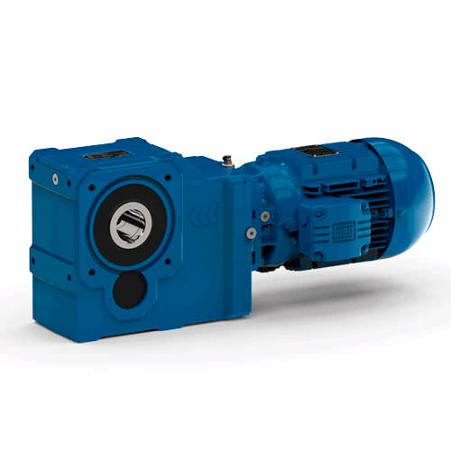 | Electric Gear Motor Three Phase 0.75 KW Bevel Helical Geared Motor, For Industrial Power 0.75 KW Rated Speed 90 RPM Phase Three Phase Usage/Application Industrial Body Material CAST IRON Model No WITH OUTPUT FLANGE Surface Treatment... View product → |
Frequently asked questions
How does a bevel helical gearbox increase torque?
The bevel stage turns the shaft direction through 90 degrees, while helical stages reduce speed progressively and increase output torque.
How do you calculate the torque an industrial machine needs?
Use the driven load, output speed, transmission efficiency and the force or power required, then account for the applicable service factor.
Why must starting, braking and reversing loads be included?
These events can impose torque peaks and shock loads that exceed the continuous running torque and damage an undersized gearbox.
How do you check whether a gearbox can handle continuous high torque?
Compare the machine’s continuous operating torque and duty cycle with the gearbox’s rated torque and thermal capacity.