A gearbox selected from motor nameplate torque alone can overheat, fail during acceleration, or deliver the wrong shaft speed. By calculating the real output torque, reduction ratio, thermal demand and application loads, you can compare catalog ratings and specify a gearbox that survives the duty.
Key takeaways
- Calculate required output torque at the driven shaft’s actual operating point.
- Set reduction ratio by dividing motor speed by required output speed.
- Check rated torque, efficiency and thermal capacity as one selection.
- Specify load type, duty cycle, backlash, shafts and holding requirements.
Calculate the torque your driven shaft actually needs
A gearbox output rating starts with the torque demanded at the driven shaft, not the motor’s nameplate torque. Calculate it in newton-metres at the shaft’s actual operating point.
Use force and radius in consistent units: load torque = force (N) × radius (m). For a vertical lift, include the load’s weight force; for a drum or sprocket, use the effective pulling force at its pitch radius.
Calculate the required output torque in these steps:
- Add the load torque to friction torque from bearings, seals, guides, and the transmission. If friction is given as a coefficient, calculate friction force first, then multiply it by the relevant radius.
- Calculate acceleration torque as J × α, where J is the total rotational inertia reflected to the gearbox output shaft in kg·m² and α is angular acceleration in rad/s².
- Add steady running and acceleration demands: Traw = load torque + friction torque + acceleration torque.
- Multiply the result by the selected service factor to cover shock, starts, jams, and duty severity: required output torque = Traw × service factor.
Check continuous torque against running demand and peak torque against starting and acceleration demand. A gearbox that turns the load steadily can still fail during a high-inertia start. Specify acceleration time, starts per hour, and the highest transient torque; do not hide those demands inside an average value.
Convert output speed into the right reduction ratio
Use the speed the motor will actually deliver, not only its nameplate rpm: reduction ratio = motor speed ÷ required gearbox output speed. A 1,440 rpm motor driving a shaft at 60 rpm therefore needs about 24:1.
At fixed-frequency operation, use the loaded motor shaft speed, because induction-motor slip reduces rpm below synchronous speed. With a VFD, estimate motor speed from commanded frequency relative to base frequency, then allow for slip under load. Confirm the motor’s permitted speed range and minimum frequency; below base frequency, available cooling and continuous torque can fall.
Above base frequency, field weakening reduces available torque, so do not assume the same performance at every speed.
- Compare the catalog’s nominal ratio versus actual ratio. A listed 24:1 ratio can be a standardized rounded value; the exact ratio comes from worm starts and wheel tooth count.
- Calculate actual output speed as actual motor rpm ÷ actual gearbox ratio. Verify that rpm when conveyor line speed, indexing or synchronization matters.
- Check the VFD’s commanded frequency at the real operating point, rather than sizing from the motor’s rated frequency alone.
A higher reduction ratio lowers output speed and normally increases available torque, but it also increases sliding losses and heat. Do not choose the ratio from speed alone: confirm that the gearbox’s torque and thermal ratings cover continuous operation and acceleration at the actual speed.
Check torque rating, efficiency and thermal capacity together
Compare the gearbox with continuous torque and thermal capacity first; then verify starting torque and peak torque against the mechanical rating. A catalogue’s larger torque figure may describe tooth strength, while the thermal rating limits heat removal during continuous sliding contact.
| Demand | Compare it with | If you miss the limit |
|---|---|---|
| Continuous torque | Continuous mechanical and thermal ratings | Oil overheats, viscosity falls and gear wear accelerates |
| Starting torque | Permissible starting torque and motor pull-up torque | Teeth or shafts can be damaged during acceleration |
| Peak torque | Permissible peak torque for jams, shocks and transients | A brief overload can cause immediate tooth failure |
Estimate output torque as T_out ≈ T_motor × ratio × worm-gear efficiency, not as motor torque multiplied by ratio alone. For motor power, use T = 9550 × P ÷ n in N·m, then apply efficiency losses and the required service factor.
Use the manufacturer’s service factor table inputs: load classification, operating hours, starts per hour, acceleration time, shock level, ambient temperature and duty cycle. A high-inertia load can make starting torque exceed running torque, even when continuous torque appears safe.
Check the thermal rating at the actual output speed and ambient temperature. Low-speed VFD operation can reduce both motor-fan cooling and gearbox heat dissipation; specify motor derating, independent cooling or a larger thermal rating when the duty is continuous. A higher ratio increases torque but also reduces speed and usually increases worm losses.
Test the selection against heat, shafts, backlash and load holding
A torque-and-ratio match can still fail when heat, shaft loading, positioning accuracy, or load holding exceeds the gearbox’s limits. Check each condition against the manufacturer’s selection data before approving the model.
| Check | What to verify | What goes wrong |
|---|---|---|
| Thermal capacity | Compare continuous duty, ambient temperature, starts per hour, and output speed with the thermal rating, not only the mechanical torque rating. VFD low-speed operation reduces self-cooled motor airflow and gearbox oil churning. | The gearbox overheats even though its mechanical torque rating appears adequate. Motor derating, independent cooling, or a larger gearbox may be necessary. |
| Shaft loading | Calculate radial and axial shaft loads from the actual pulley, sprocket, belt, or chain force and its distance from the bearing. | Bearing overload, shaft bending, or seal failure occurs despite correct torque. |
| Backlash and repeatability | Specify allowable angular backlash and required repeatability for reversing, indexing, positioning, or load-holding duty. | Wear increases lost motion, so the mechanism stops short or returns inconsistently. |
| Backdriving | Check whether the load can drive the worm shaft during stopping or power loss. | A suspended load descends. Use a brake or mechanical holding device unless the supplier confirms self-locking under the exact load and ratio. |
| Lubrication and mounting | Confirm oil type, fill level, ambient range, and approved mounting orientation. | Incorrect orientation starves gears or bearings, causes leakage, and accelerates wear. |
Intermittent duty does not justify an informal average-power calculation. Use the manufacturer’s duty-cycle and thermal calculation, especially for frequent starts, reversals, or continuous low-speed running.
Prepare a gearbox specification that a supplier can verify
Put the request in operating terms, not simply “worm gearbox.” Give the supplier a completed gearbox selection checklist:
1. State required output speed in rpm, required continuous output torque in N·m, starting or peak torque, acceleration time, load inertia, direction of rotation, and required reduction ratio. Include the calculated service factor and the maximum acceptable backlash.
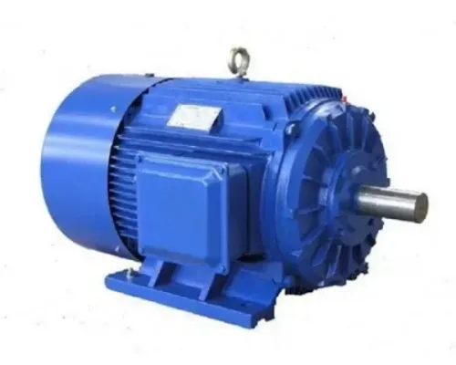
2. Identify the motor by power, rated speed, rated torque, frame size, shaft diameter, shaft length, keyway, mounting flange, supply voltage, frequency, and brake arrangement. Add the VFD model, base frequency, operating speed range, lowest continuous speed, and whether independent motor cooling is fitted.
3. Describe the duty: hours per day, continuous or intermittent operation, starts per hour, reversing frequency, shock loads, jam conditions, and acceleration cycles. Request confirmation that both thermal capacity and permissible peak torque cover these conditions.
4. Specify ambient temperature, indoor or outdoor location, dust, water, washdown chemicals, altitude, and enclosure requirement. Name the oil grade and viscosity, manufacturer-approved bronze-compatible additives, fill level, drain and vent arrangement, and low-temperature range.
5. State mounting position, foot or flange installation, output shaft orientation, radial and axial loads, shaft coupling, and available space. Mounting position must be verified before purchase because it changes oil coverage and venting.
Ask Perfect Engineering Solutions to return the proposed model, ratio, rated and peak torque, thermal rating, oil specification, dimensions, and motor-and-gearbox verification against every item.
Related products
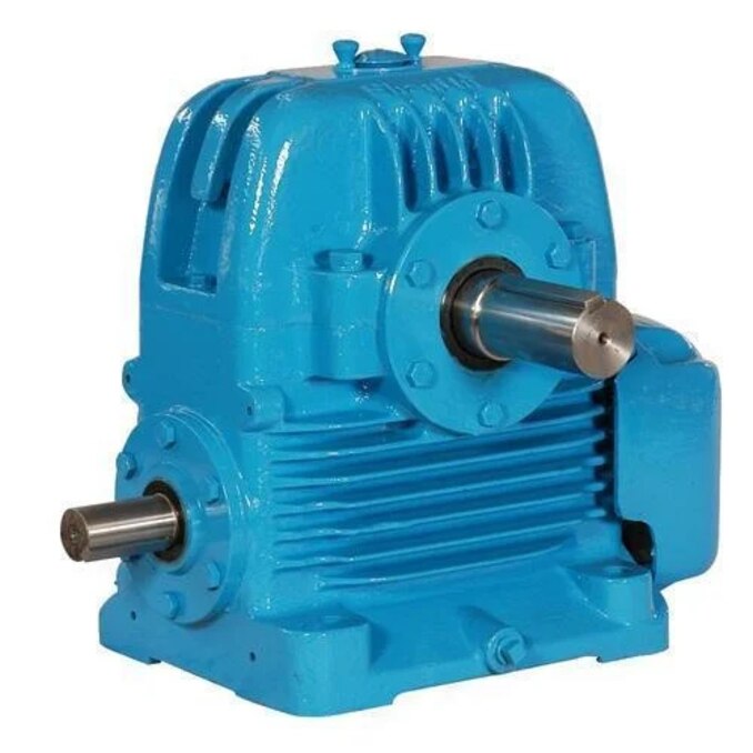
 | WORM GEARBOX ₹100000 PERFECT ENGINEERING SOLUTIONS WE HAVE WIDE RANGE PRODUCTS OF MOTOR, GEARBOX, PUMPS , VFD DRIVES , CABLES, ETC... View product → |
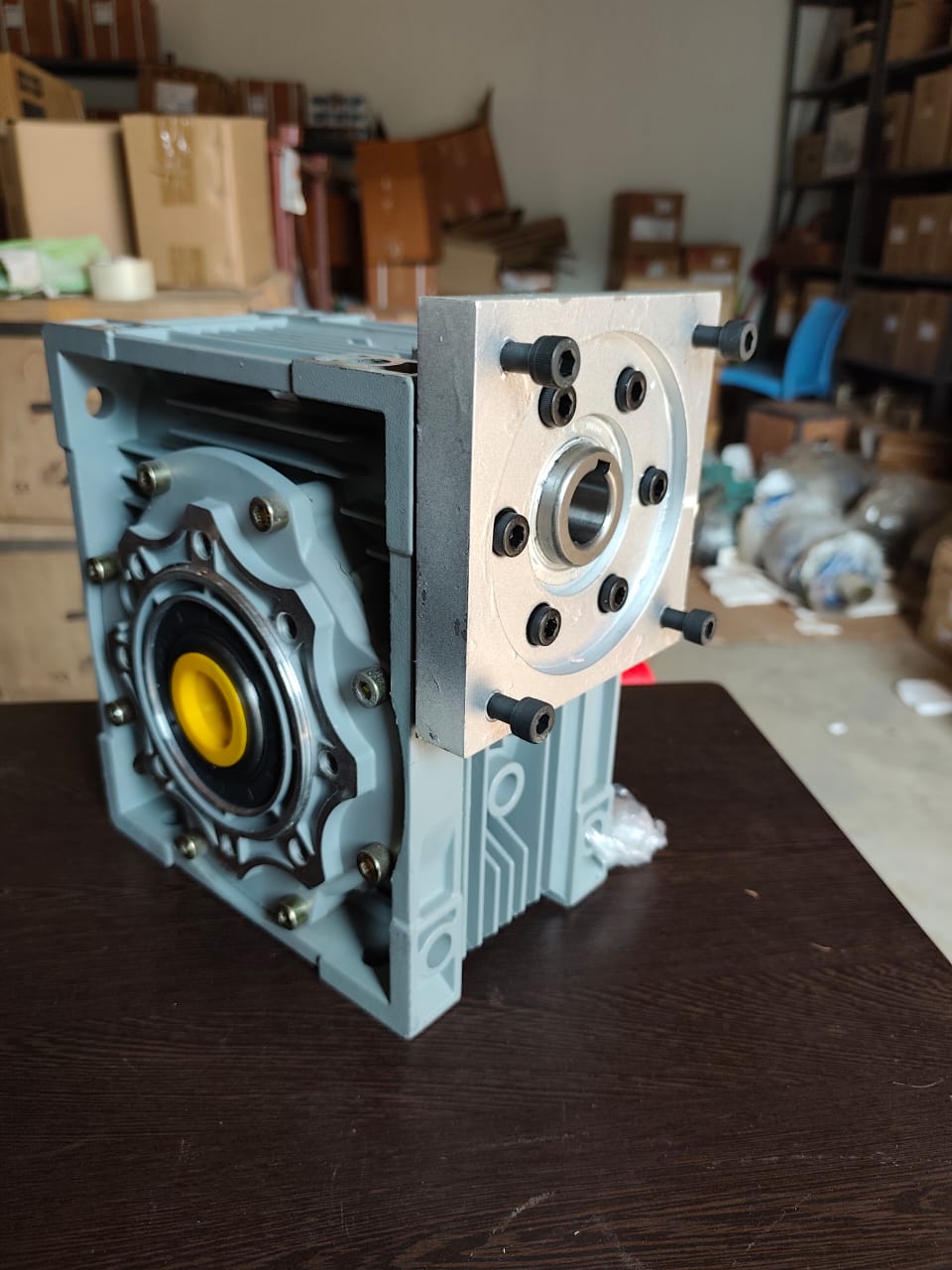 | SERVO MOTOR CONNECTED WORM GEARBOX SERVO MOTOR CONNECTED WORM GEARBOX ₹18000 servo gearbox is a precision-engineered gear system designed to work with servo motors, enhancing torque output while maintaining high positional... View product → |
Frequently asked questions
How do you calculate the torque a worm gearbox must deliver?
Calculate the torque demanded at the driven shaft in newton-metres at its actual operating point, then account for starting, shock and service loads.
How do you choose the reduction ratio for a worm gearbox?
Divide the motor speed by the required output speed. Confirm that the resulting ratio matches an available gearbox ratio and the application’s operating range.
Why must torque rating, efficiency and thermal capacity be checked together?
A gearbox can meet the torque figure yet overheat when losses, duty cycle, ambient temperature and continuous operation exceed its thermal capacity.
What should you test before selecting a worm gearbox?
Check heat rise, shaft loads, backlash, lubrication, shock loading and whether the gearbox must hold a load when power is removed.
What information should a gearbox specification include?
State motor speed and power, output speed, required torque, duty cycle, load type, starts per hour, ambient temperature, mounting position, shaft details, backlash and load-holding requirements.
Related products
 | Electric Motor ₹5100 Gear Type Worm Material Aluminium Orientation Horizontal Mounting Flange Output Torque 350Nm Input Speed 1400 rpm WORM GEARBOX W SERIES... View product → |
 | Gear Box 0.5 Iron Worm Gear Box, Size: 30-150 ₹4500 Material Cast Iron Power 0.5 Gearing Arrangement Type Worm Size 30-150 Orientation Horizontal Mounting Foot View product → |
 | Geared Motor ₹8500 Power 0.37 KW Rated Speed 90 RPM Phase Three Phase Usage/Application Conveyors Voltage 415 Mounting Flange Mounting Number Of Poles 4 Poles Country... View product → |
 | Geared Motor ₹284000 Motor Power 30HP Motor Speed 60 RPM Gear Type Helical Orientation Horizontal Mounting Foot Usage/Application Conveyors Phase 3PHASE Material CI Input... View product → |