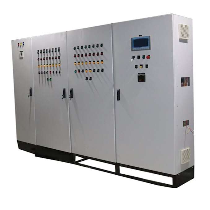
A PLC panel coordinates sensors, logic, motor starters, VFDs, valves and operator commands, but it does not replace the protective and safety equipment that makes a machine electrically sound. By the end, you will be able to map the control sequence, choose a suitable architecture, size the I/O and power systems, and compare the panel details that affect reliable operation.
Key takeaways
- Map every sensor and actuator signal before selecting PLC I/O.
- Separate protective circuits from ordinary machine control logic.
- Match VFD ratings, motor data and PLC communication methods.
- Inspect enclosure rating, terminal labels, earthing and test records.
How the PLC Panel Turns Signals into Machine Actions
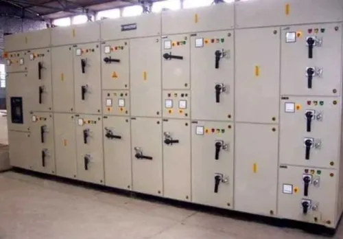
The incoming supply enters the PLC panel through a main isolator and circuit breakers. Protective devices divide power between the PLC, 24 V DC power supply, motor circuits and VFDs, while terminal blocks organise field wiring and the earthing bar bonds the enclosure, equipment earths and protective conductors.
1. A 24 V DC proximity sensor or pressure switch changes state when a target arrives or pressure reaches its setpoint. That signal reaches a digital input module through labelled terminal blocks. Transmitters provide an analogue input 4–20 mA and 0–10 V; RTD modules measure temperature.
2. During each scan, the PLC CPU reads the input image, executes ladder logic or function-block logic, and checks permissives, interlocks, timers and analogue limits. The HMI displays states, setpoints, alarms and faults, but it does not replace hardwired safety functions.
3. An output module then energises an interposing relay, contactor or solenoid valve, or sends a run and speed command to a VFD. A 0–10 V reference sets speed, while the drive controls motor frequency and voltage. Alarm outputs operate beacons, horns or external signals.
4. Auxiliary contacts and VFD feedback return running, fault, ready and stopped status to digital inputs. The PLC blocks a restart when feedback disagrees with the command.
5. PLC logic is separate from motor power control. Contactors switch power, overload protection and motor-protection circuit breakers protect circuits and motors, VFDs control speed, and safety circuits handle emergency stops; a standard PLC output is not an emergency-stop device.
Choose the Control Architecture That Fits the Machine
Choose by machine count, I/O location, response time, data retention, operator access, maintenance skill and future expansion—not by PLC price alone.
| Option | What it means | When it applies |
|---|---|---|
| Compact PLC | CPU and fixed I/O in one unit | Small machine with fixed digital I/O, a few analogue points and local control |
| Modular PLC | Expandable rack with mixed modules | Growing machine, mixed analogue, digital, RTD or communication signals |
| Relay logic | Hardwired relays, timers and contactors | Simple sequence with little diagnostic, recipe or data demand |
| VFD-only control | Drive terminals handle run, stop and speed | One motor needing speed control and basic permissives |
| Remote I/O | Field signals connect to a nearby I/O station | Sensors and valves are spread across the machine; it reduces long multicore cable runs |
| SCADA | Supervisory software over controllers | Multiple machines, historian data, supervisory alarms, trends and operator access |
Use a compact PLC when a small fixed-I/O machine needs diagnostics and timers. Choose a modular PLC when expansion, mixed signal types or replacement modules matter. Relay logic is economical for a simple sequence, but troubleshooting and recipe changes become difficult.
A VFD-only arrangement fits one motor; add a PLC when sequencing, interlocks or several devices enter the job.
Use remote I/O when field devices are distant but one controller still suits the process. Use a networked PLC with distributed panels when several areas need local control, isolation and scalable communications.
Specify the communication-loss response: timeout, commanded state such as controlled stop, fault-reset policy and restart inhibit. Never leave the last speed reference active after a network failure. SCADA supervises; it does not replace local interlocks or safety circuits.
Size the PLC, I/O, Power Supply and Protection Together
Start with an I/O schedule, not a PLC model. List every digital input, digital output, analogue input, analogue output, RTD channel and spare point; allow spare I/O points for added sensors, alarms and future equipment. Then check PLC scan time against the fastest required response.
Calculate the 24 V DC power supply load from the PLC, sensors, relays, solenoid valves, communication devices and VFD control circuits. Include inrush current and state a defined spare capacity, or a valve bank can collapse the control voltage during a cycle.
Count every VFD and motor, record each motor’s nameplate current and starting method, and separate continuous load from rapid starts, repeated cycling, regenerative braking and high-inertia stopping. A modest motor can still make the braking resistor or drive the panel’s dominant thermal load.
- Select branch fuses or miniature circuit breakers, short-circuit protection, control transformers or DC supplies, and protective conductors as one coordinated system.
- Specify communication ports and protocols only after identifying which devices exchange run, speed, status and fault data.
- Check enclosure heat, conductor ratings and the real machine duty cycle, not only steady-state current.
- Evaluate the assembly short-circuit rating for the complete panel and protective-device combination. Do not copy the interrupt rating from one breaker or VFD label; that figure does not automatically rate the finished assembly.
This approach leaves expansion space without buying an oversized controller, while preventing nuisance trips, voltage dips and overheating during the cycle that matters.
Integrate Motors and VFDs Without Confusing Control with Safety
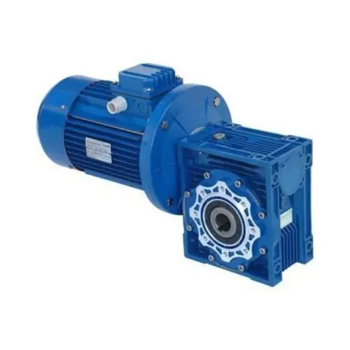
Use the PLC for sequencing, not as a substitute for protection. For each three-phase motor, geared motor or pump, define the command path, feedback path and safe stopping method before wiring the panel.
1. Map hardwired or networked run and direction commands to the drive. Use a 0–10 V signal or network speed reference, and return ready, running and drive-fault status. Include motor-overload and process interlocks, such as low level, pressure loss or a closed valve, so a permissive failure removes the run command.
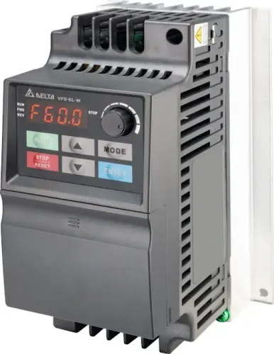
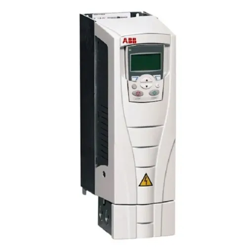
2. Select an ABB ACS560 VFD from motor nameplate current, overload duty, speed range, supply voltage, braking duty and installation conditions—not motor kW alone. Enter the nameplate voltage, current, frequency, speed and power-factor data into the electronic motor-overload model.
A thermal overload relay installed only on the VFD input does not protect the motor correctly during variable-speed operation.
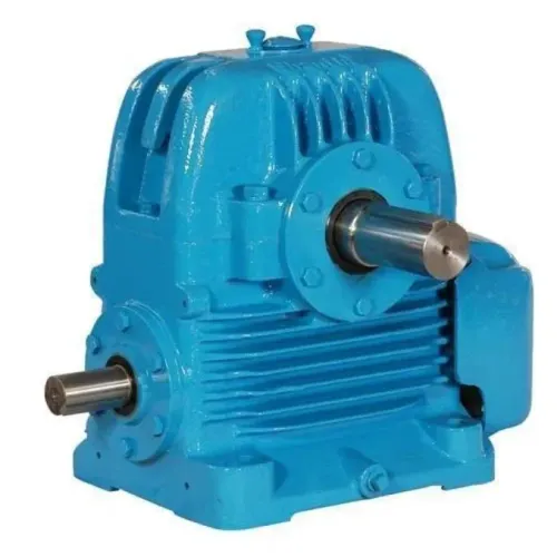
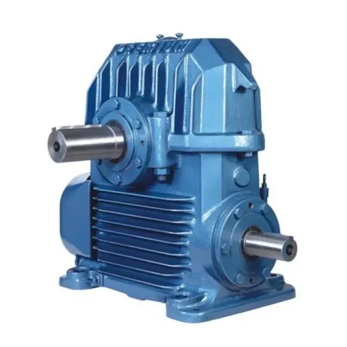
3. Check the installation before commissioning. Low-speed gearmotors may need an independently powered cooling fan; long motor leads may require a dV/dt filter or sine-wave filter. Use inverter-rated motors and terminate cable shields over a broad area.
Add a braking resistor when high-inertia loads, hoists or overrunning gearboxes return energy to the DC bus; size it for peak power, pulse duty and heat dissipation.
A PLC stop is not an emergency stop. Risk assessment may require dual-channel guard circuits, monitored contactors or certified Safe Torque Off, plus a disconnect and mechanical brake where needed. Interlock every bypass so the VFD output contactor and bypass starter cannot connect together.
Compare the Panel’s Enclosure, Wiring and Commissioning Details
Maintainability and cooling depend on the complete assembly, not the PLC brand. Compare painted mild steel with stainless steel for corrosion exposure, then specify the PLC panel enclosure IP rating, usable dimensions, gland plate, cable-entry direction, ambient-temperature rating and separate earthing points. A listed motor IP55 rating does not prove the completed panel is IP55.
| Design choice | Benefit | Main risk |
|---|---|---|
| Sealed enclosure | Better dust and humidity protection | Prevents natural convection; VFD heat dissipation raises internal temperature |
| Filtered fan | Removes heat at moderate cost | Filter loading reduces airflow and requires cleaning |
| Heat exchanger | Keeps internal air sealed | Adds cost and needs correct temperature sizing |
| Air conditioner | Handles high heat loads | Highest cost and maintenance |
| Larger derated enclosure | Simpler, cooler operation | Requires more floor or wall space |
Include VFD losses in the thermal calculation. Separate mains, VFD motor cables, analogue signals, safety wiring and communications using ducts, screened-cable practice and physical spacing; this is power and control wiring segregation, not merely neat routing.
Require labelled terminals, ferrules, wire numbers, as-built drawings, an I/O list, PLC and VFD backups, fault descriptions and a clearly identified main disconnect. Specify the gland plate and cable entries from the machine side to avoid crossing control wiring.
PLC panel commissioning must verify, before autotuning:
- Motor voltage, current, frequency, base speed, and star or delta connection.
- Uncoupled rotation where practicable, followed under load by acceleration, current, direction, brake release and gearbox lubrication.
- Interlocks, emergency-stop behavior, communication-loss timeout, commanded state, reset policy and restart inhibit.
Perfect Engineering Solutions can separate PLC configuration, power-control equipment, VFD integration, enclosure construction and commissioning in its quotation. Verify the panel rating independently, especially where a VFD description combines 415 V three-phase service with 230 V input details.
Related product
 | MOTORS#GEARBOX#VFD DRIVES#PUMPS#CONTROL PANELS#AUTOMATION PANELS., MOTORS#GEARBOX#VFD DRIVES#PUMPS#CONTROL PANELS#AUTOMATION PANELS., View product → |
Frequently asked questions
How does a PLC panel turn signals into machine actions?
Field sensors send input signals to the PLC, which executes programmed logic and switches outputs to actuators, contactors or VFD commands.
How do you choose a PLC control architecture?
Choose centralised or distributed I/O, hardwired or networked control, and the required communication protocol based on machine layout, signal count and future expansion.
How should you size PLC panel components?
Count digital and analogue I/O, allow spare channels, calculate 24 V DC load, and coordinate breakers, power supplies, cable sizes and short-circuit protection.
How should motors and VFDs integrate with a PLC panel?
Define start, stop, speed reference, feedback and fault signals separately, then keep emergency stopping and other safety functions on an appropriate safety circuit.
What panel details should you compare before commissioning?
Compare enclosure protection, ventilation, wire ferrules, terminal labels, earthing, separation of power and control wiring, drawings and documented functional tests.