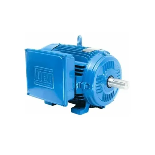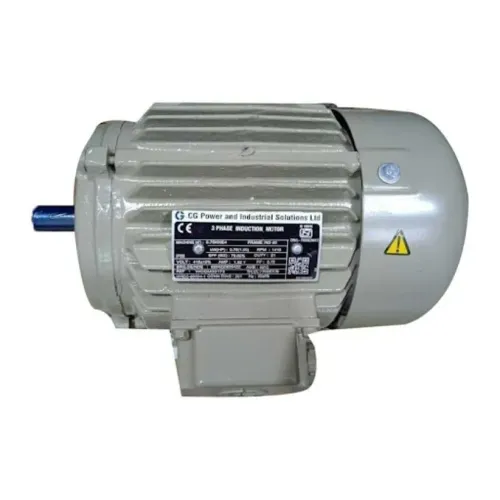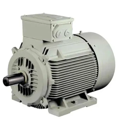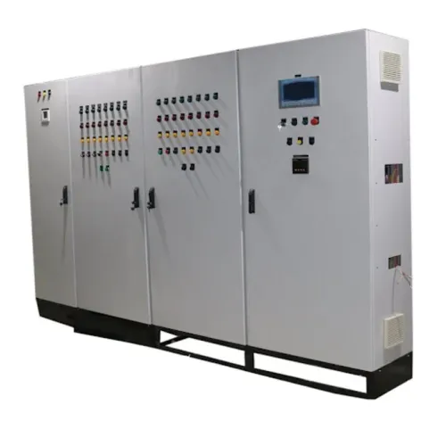
Motor speed depends on more than entering a frequency into a drive: the motor’s rated current, load torque, wiring, cooling and control method all determine whether the installation runs safely. By the end, you will be able to assess ACS560 compatibility, choose a drive size, plan commissioning and judge whether speed reduction will produce real energy savings.
Key takeaways
- Size the ACS560 from motor nameplate current and duty, not motor horsepower alone.
- Confirm the 415 V supply, earthing, motor wiring, and protective devices before commissioning.
- Use scalar control for simple loads and vector control when torque response matters.
- Energy savings are strongest on variable-torque fans and pumps, not constant-power loads.
How output frequency and voltage set induction-motor speed
An ABB VFD controls an induction motor by synthesising a three-phase PWM waveform. Its output frequency sets the speed of the motor’s rotating magnetic field, while output voltage supplies the magnetic flux and torque needed by the load.
Up to the motor’s base frequency, the drive normally raises voltage with frequency to maintain an appropriate volts-per-hertz ratio.
The synchronous speed formula is Ns = 120f/P, where Ns is speed in revolutions per minute, f is output frequency in hertz and P is the motor’s pole count. The shaft never quite reaches Ns: an induction motor needs slip, the speed difference that induces rotor current and produces torque.
| Operating condition | What the drive controls | What happens at the shaft |
|---|---|---|
| Below base frequency | Frequency and proportional voltage | Speed follows the reference but falls with load because slip increases |
| At rated frequency | Base frequency and rated voltage | Rated speed is lower than synchronous speed by the nameplate slip |
| Above base frequency | Frequency continues rising, voltage is limited | Field weakening reduces available torque; a constant-torque load can overload the motor |
Therefore, commanded speed differs from actual shaft speed because load torque, voltage drop, motor heating and parameter accuracy change slip. Sensorless vector control estimates these effects; correct nameplate voltage, current, frequency, speed and power factor data, followed by the appropriate motor identification run, improves the estimate.
A rotating identification run requires a safe coupling and load. An encoder is needed when the application demands measured, tightly regulated shaft speed.
How to size an ACS560 from motor current and duty
A 7.5 kW motor is not automatically a 7.5 kW ACS560 selection. Start with the motor rated current, also called full-load current, because two motors with the same kW can draw different current due to power factor, efficiency, winding design and rated speed.
| Motor or site detail | Why it changes ACS560 selection |
|---|---|
| Motor voltage, phase and 50 Hz base frequency | The drive output and motor connection must match; incorrect star or delta links can produce low torque or excessive current. |
| Motor rated current and overload requirement | Compare the nameplate current with the ACS560 output-current rating, not only its kW label. |
| Normal-duty and heavy-duty rating | Pumps and fans may suit normal-duty loading; conveyors, crushers and loaded hoists need heavy-duty overload capacity and starting torque. |
| Duty cycle and acceleration time | Frequent starts, short ramps and long overload periods increase thermal stress and can require a larger current class. |
| Ambient temperature, altitude and enclosure airflow | Heat, thin high-altitude air and restricted ventilation reduce allowable drive current; use the ACS560 rating tables for the actual installation. |
| Load inertia and stopping method | High-inertia deceleration can raise DC-link voltage. Check for a braking chopper and resistor; a larger drive alone will not fix inadequate braking. |
| Incoming supply and enclosure arrangement | Confirm the required three-phase input, protection, ventilation and physical space before ordering. |
Perfect Engineering Solutions can compare the motor nameplate, measured running current and machine duty against the ACS560 rating table. Do not select from gearbox kW alone: gearbox ratings describe transmitted mechanical power, not the drive’s current and overload capability.
Related product
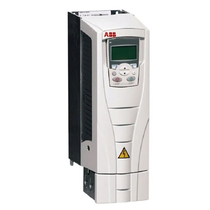
 | ABB VFD Drive ACS560 ABB VFD Drive, 3 - Phase, 415V Brand ABB Model Name/Number ACS560 Motor Power 415V Input Voltage 230V Input Phase 3 - Phase ABB VFD for Various Industrial Applications. View product → |
How to verify the 415 V installation and commission it safely
Confirm the incoming supply is a 415 V three-phase system within the ACS560 nameplate voltage range, with stable phase-to-phase readings and a correctly sized protective earth. Isolate and lock out the circuit before opening the drive; never megger-test through the connected VFD.
- Compare the drive nameplate with the measured supply, then verify upstream fuses or circuit breaker, short-circuit rating, earthing, enclosure ventilation and required derating for ambient temperature, altitude, carrier frequency and overload duty.
- Read the motor nameplate and fit its links for the drive’s output voltage. Enter rated voltage, current, kW, frequency, rpm and power factor as required; confirm the 50 Hz motor connection matches the selected 50 Hz operating data.
- Check that incoming conductors land only on the line terminals and the motor conductors only on the motor terminals. Tighten each connection to the manufacturer’s torque specification and inspect for stray copper strands.
- Use the specified shielded motor cable, bond its shield with a continuous 360-degree termination at both drive and motor ends, and arrange the protective conductor exactly as the ABB manual shows. A drain wire or one-end shield bond is not equivalent.
- Check cable length against the drive limit and install a du/dt or sine-wave filter when ABB or the motor maker specifies one. Confirm the brake resistor and chopper rating for high-inertia stopping.
- Set minimum and maximum frequency, acceleration, deceleration, stop mode, motor thermal protection, current limit and control source before a no-load test. Interlock any bypass or output contactor so it cannot switch while PWM output is active. Start at low speed and verify rotation, current, noise and trip-free stopping.
Which control method and speed reference suit the machine
Choose the control mode from the machine’s torque and speed-regulation demands, not from the motor’s kW rating alone. A fan or centrifugal pump rarely needs elaborate torque control; a conveyor, mixer or extruder may need strong low-speed torque.
| Option | What it provides | When it applies |
|---|---|---|
| V/Hz control | Fixed voltage-to-frequency relationship and simple commissioning | Fans, pumps and predictable loads whose torque demand changes little |
| Sensorless vector control | Estimated motor speed, improved low-speed torque and tighter speed regulation without an encoder | Conveyors, compressors, mixers and loads with changing torque; complete motor data and an identification run first |
| Vector control with encoder | Measured shaft speed and precise torque or speed control, including near-zero speed | Hoists, lifts, winders and positioning machines where slip estimation is not accurate enough |
Incorrect nameplate voltage, current, frequency, speed or power factor data can make sensorless vector control hunt, overheat the motor or deliver weak starting torque. A rotating identification run also requires the coupling and load to be safe for movement.
Above base frequency, voltage is already limited, so torque falls as speed rises; do not command high speed on a constant-torque load without checking the motor and drive ratings.
Give the drive separate run, stop, direction and fault-reset commands through digital inputs or a fieldbus. Use a 0–10 V speed reference for a nearby operator potentiometer or controller, with defined minimum and maximum scaling.
Use 4–20 mA PLC communication for longer wiring or industrial control; configure signal-loss action, ramp times and overspeed limits before enabling automatic operation.
When speed reduction delivers energy savings—and when it does not
Estimate savings from the actual operating point, not the motor’s nameplate kW. For a centrifugal fan and pump affinity laws, speed at 80% predicts flow at 80%, head at 64%, and ideal shaft power at 51.2%. Static head, minimum flow, throttled valves and system efficiency can reduce that result sharply.
- Record present kW, operating hours and load profile, then compare them with the ABB VFD’s measured input kW at each proposed speed. Include drive losses, motor efficiency and any auxiliary cooling power.
- Check whether the motor runs above base frequency. In field weakening, speed rises while available torque falls; the process may demand more torque than the motor can deliver, eliminating the expected saving.
- Verify low-speed cooling and torque. A self-cooled motor’s shaft fan moves less air at reduced speed, so continuous operation may require derating or a separately powered blower. A gearbox increases output torque, but does not remove the motor’s input-torque or lubrication limits.
- Confirm the gearbox ratio, oil lubrication, bearings, brake release and the driven machine’s minimum speed. A better ratio can outperform very low motor frequency, while excessive ratio can force high-speed field weakening.
- Calculate deceleration energy for high-inertia loads. A braking resistor and suitable chopper dissipate it; regenerative braking returns it to the supply. Neither option saves energy during steady running, and an undersized braking system causes DC-link overvoltage trips.
A six-pulse drive also creates input-current harmonics. A line reactor or DC-link choke reduces peaks, but strict limits can require an active harmonic filter or regenerative front end after a site impedance study. That assessment separates genuine energy efficient industrial operations from apparent savings that shift losses elsewhere.
Frequently asked questions
How does an ABB VFD control induction-motor speed?
The drive sets output frequency to control the rotating magnetic field speed and adjusts voltage to maintain motor flux and torque.
How should you size an ABB ACS560 for a motor?
Match the drive’s rated output current to the motor nameplate current and select a duty rating that covers the machine’s starting, overload, and braking demands.
What must you verify before commissioning a 415 V ABB VFD installation?
Check the incoming voltage, protective devices, earthing, motor connections, cable arrangement, insulation condition, and parameter settings before running the motor.
Which ABB VFD control method suits an industrial machine?
Choose scalar control for straightforward pumps, fans, and conveyors; use sensorless vector control when the machine needs stronger low-speed torque or tighter speed regulation.
When does reducing motor speed save energy?
Speed reduction delivers the largest savings on variable-torque fan and pump systems; it does not guarantee savings when production output, static pressure, or constant torque must remain unchanged.